The end-device node in kunjctl is supposed to run on a battery. The whole reason it deep-sleeps for 15 seconds out of every 18 is to make the battery last. The radio is off 99% of the time. The CPU runs at 32 MHz. The firmware is careful about every microamp.
In winter, a 10000 mAh power bank lasted about a day and a half.
The culprit was the relay. A standard non-latching relay holds its contacts closed by continuously energizing a coil. The one I had drew about 100 mA at 3V the entire time the relay was on. Deep sleep was scraping for microamps. The relay was burning a hundred milliamps next to it, all day, every day. The microamp work was a rounding error.
The fix is a different kind of relay. It came with a schematic to design, a small board to build, and a firmware change to write. The mechanical part of the story turned out to be the easy half.
Repo: github.com/kaiwalya/kunjctl. Hardware lives under pcbs/end-device-hfe60/, firmware change in thread-end-device/src/outputs/relay.c.
Why a latching relay changes the energy story
A latching relay holds its mechanical state with no power at all. There are two coils inside it: one to flip the contacts to ON, one to flip them back to OFF. You pulse the appropriate coil for a few tens of milliseconds, the contacts physically move, and they stay there. After the pulse, both coils are de-energized. The relay holds itself.
A 50 ms pulse at 100 mA is about 1.4 µAh of charge (or, at 3 V, about 4.2 µWh of energy). On the 10000 mAh bank, that is roughly one part in seven million. You could toggle the relay every minute, all day, for years, and the relay subsystem would still not be the thing that drains the battery.
Compare that to the old relay. 100 mA, continuously, for as long as the relay was on. An hour of “on” was 100 mAh, or 1% of the bank. A day of “on” was a quarter of it. Most of my use cases want the relay on most of the time, so the answer was: the bank empties in a day and a half.
The board
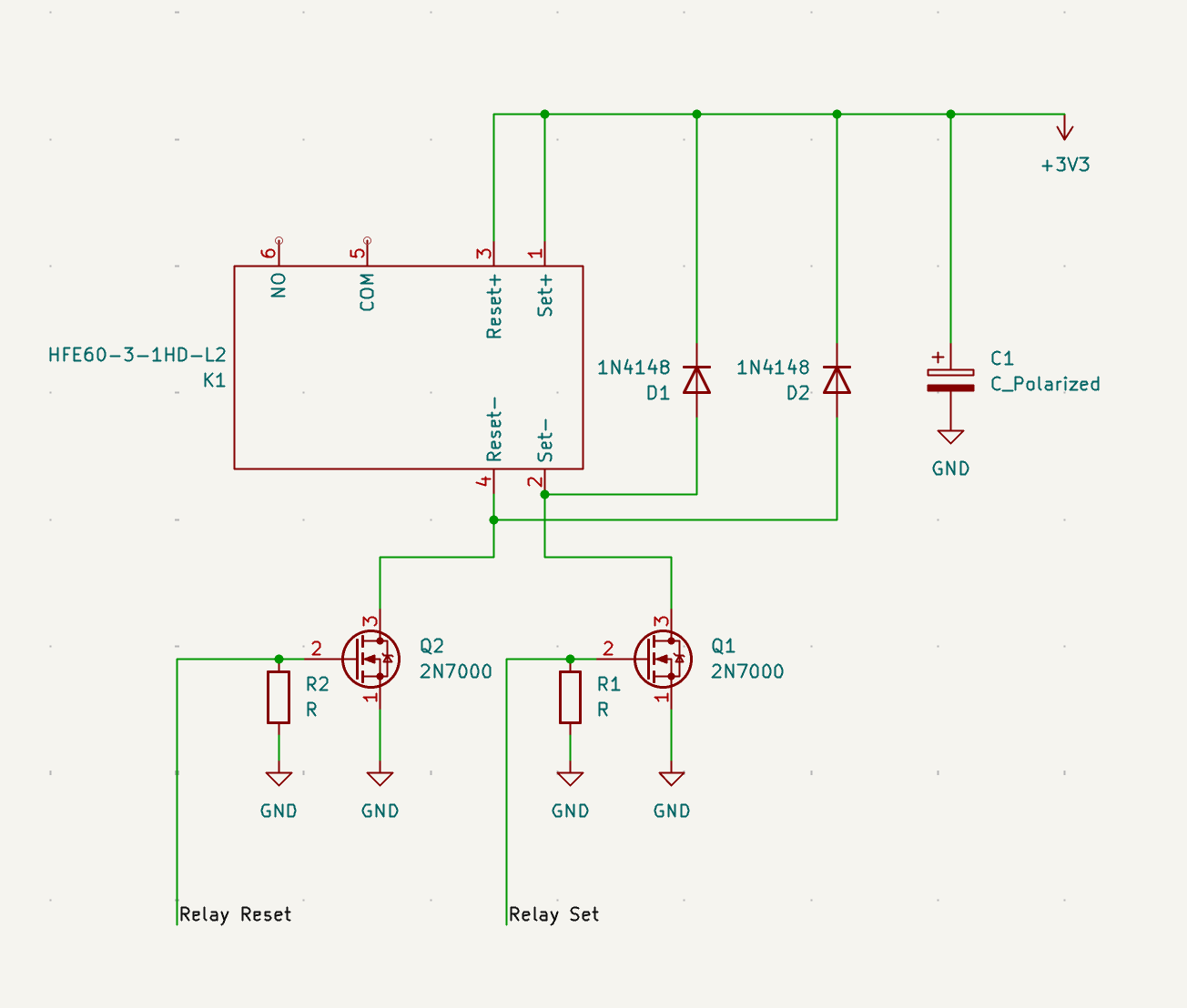
I had to learn KiCad to do this. The relay is a Hongfa HFE60-3-1HD-L2, a 3V double-coil latching part. The driver topology is two N-channel MOSFETs (2N7000) as low-side switches, one per coil. GPIO drives a gate high for the configured pulse duration (CONFIG_RELAY_PULSE_MS, 50 ms in our build), the MOSFET conducts, the coil energizes, the relay flips. GPIO returns low, the MOSFET opens, the coil de-energizes, the relay holds.
Each coil gets its own driver because the datasheet forbids energizing both coils at once. There is no clever way to share a single transistor between them.
The gate is a capacitor, not a resistor
The MOSFET gate is not a wire. It is a tiny insulated plate sitting over the channel, separated from it by a thin layer of silicon dioxide. There is no DC path from the gate to the source, drain, or anywhere else. The gate behaves like one plate of a capacitor.
The way the FET turns on: pile up charge on the gate, the resulting voltage attracts carriers in the channel underneath, the channel becomes conductive. To turn off, you remove the charge. The gate is not “consuming current” while it is on; it is holding charge on a capacitor, and the channel below is conducting because of the voltage that charge implies.
This explains a lot of behavior that otherwise looks weird:
- A floating gate (no driver attached) will drift to whatever voltage stray fields and leakage push it to. Pick up a 2N7000 with the gate dangling and put your finger near it: the finger’s induced field can push the gate above threshold and the FET partially turns on. You can watch this on a multimeter.
- A gate that was driven high stays high after the driver disconnects, because there is nowhere for the charge to go. It will hold for seconds, even minutes, depending on leakage.
So when the GPIO driving the gate is floating, which happens during boot, before gpio_set_direction runs, and briefly during deep sleep transitions, the gate sits at some random voltage somewhere between 0 and the supply rail. That can drain the battery (FET partly on, current flowing through the coil) and may half-engage the relay.
The fix is a 100 kΩ resistor from the gate to GND (R1 and R2 in the schematic). It is not draining current from the gate. There is no gate current to drain in steady state. What it is doing is providing a default voltage: when no driver is attached, the resistor weakly pulls the gate to 0 V, and the FET stays definitively off.
The resistor value barely matters because the gate draws no DC current. Any value between 10 kΩ and 1 MΩ is reasonable. The choice is a tradeoff between two things:
- Too high: 2N7000 gate leakage is sub-nanoamp, so a 1 MΩ resistor is electrically fine in dry conditions. On a humid or dirty board, surface leakage on the PCB itself can dominate, and the safety margin shrinks. 100 kΩ to 1 MΩ is a comfortable range.
- Too low: when the GPIO is actively driving the gate high, the pulldown is fighting it. At 220 Ω with the GPIO at 3.3 V, the GPIO has to source 15 mA just to hold the gate above the pulldown. That is past the comfortable per-pin source limit on many ESP32 GPIOs (often spec’d around 12 to 20 mA), so the gate may not actually reach a clean V_GS, and the FET switches sluggishly. At 100 kΩ the GPIO sources 33 µA. Same FET behavior, 460× less waste, and the GPIO is doing real work instead of fighting a resistor.
A flyback diode is not optional
You can pulse the coil on the bench by touching 3V3 to its leads with your finger and it works perfectly. That is misleading. You broke the contact slowly, with your skin acting as a resistor that bled the inductive energy gradually as the contact area shrank.
A MOSFET turning off in under 1 µs is a different story. The coil’s collapsing magnetic field can generate a voltage spike of hundreds of volts with nothing to clamp it, vastly above the 2N7000’s drain-source breakdown (60 V minimum, per the datasheet). The FET goes into avalanche, dissipating real energy each time. Each event degrades it. Eventually it shorts.
A 1N4148 diode across the coil clamps the spike. It sits in parallel with the coil: cathode at the +3V3 end, anode at the drain end. D2 does this for the SET coil (with Q1), D1 does it for the RESET coil (with Q2).
When Q1 is on, current flows from +3V3, through the SET coil, through Q1 to GND. D2 is reverse-biased and does nothing.
When Q1 turns off, the coil insists on continuing to push current in the same direction (an inductor hates having its current changed). With Q1 open, the only available path is back through the diode. The drain pin tries to fly upward to maintain the current. The moment it gets ~0.7 V above +3V3, D2 forward-biases, and the coil energy circulates through the diode-coil loop until it dies out (a few milliseconds, depending on the coil’s inductance and the loop resistance). The drain pin never sees more than +3V3 + 0.7 V ≈ 4 V. The FET survives.
The diode goes across the coil. Not from drain to GND.
I made this mistake twice during schematic capture. First the diodes dangled with their anodes on GND (wrong). Then I “fixed” them so the anodes were on standalone single-pin nets (also wrong, just floating instead of misconnected).
The reason it has to be across the coil specifically: the collapsing field needs a closed loop to circulate current through. The coil is briefly a current source for those few milliseconds, and the diode-coil loop is its return path. If the diode were between drain and GND, there would be no loop through the coil at all; the spike would still appear at the drain because the coil still has nowhere to push its current. Same result as no diode.
A few small KiCad facts
PWR_FLAG looks like a real component on the schematic but is not. It is a marker telling KiCad’s electrical rules checker “this net has a power source somewhere, stop complaining.” Without it, ERC reports +3V3 and GND as undriven. It does not appear on the PCB.
GND and GNDPWR are separate nets, intended for designs that physically split signal ground from high-current power ground (audio, motor drivers, sensitive analog). For plain digital and relay work, use GND everywhere. Mixing the two creates two unconnected ground nets in the netlist.
The firmware contract changes too
A non-latching relay has a safety property that comes for free: when power is removed, the contacts open. The MCU’s GPIO defaults to low on reset, the coil de-energizes, the spring opens the contacts. Software state (a “relay is OFF” boolean in RTC memory) and physical state (contacts open) align automatically. You never have to think about it.
A latching relay holds its position mechanically with no power. After a power loss, the contacts are wherever they were when power vanished, possibly weeks ago. The MCU has no way to read mechanical state. So the boot path now has to reckon with a possibility the old firmware never had: the in-memory state and the physical state can disagree, and the only way to resolve it is to pulse a coil.
The old firmware’s behavior of “cold boot equals relay OFF” was emergent, not designed. It worked because the GPIO defaults to 0 on reset, the spring opens the contacts, and nobody had to think about it. The new firmware makes the same property explicit by deciding what state to drive the relay to on cold boot, and pulsing the appropriate coil to get there, instead of relying on a happy coincidence.
Cold boot vs deep-sleep wake
The end-device cycles every ~18 seconds (3 seconds active, 15 seconds deep sleep). That is about 4800 wakes per day. Pulsing the coil on every wake “to be safe” would wear out a relay rated for 100,000 operations in about three weeks.
The fix is to distinguish the two cases:
- Cold boot (power-on, hard reset, factory reset, brownout). The driver is being constructed from scratch. Physical relay state is unknown. Pulse the appropriate coil to drive the hardware into agreement with whatever state the application says it should boot into.
- Deep-sleep wake. Physical state is whatever we last set, because nothing has moved the contacts in the meantime. Do nothing.
Brownout is the one I want to call out explicitly. Battery sag is the realistic failure mode for a battery node, and it surfaces as a brownout reset, which is exactly the case where the in-memory state and the physical state can have drifted apart. Treating it like a cold boot (pulse to resync) is the right call.
esp_reset_reason() != ESP_RST_DEEPSLEEP is true exactly when you need to pulse: power-on, brownout, watchdog, panic, software reset, all of them.
The driver’s actual signature is two booleans:
relay_t *relay_init(bool initial_state, bool force_resync);initial_state is the state you want the relay to be in once init returns. force_resync says “I do not trust that the hardware is already in initial_state, please pulse to make sure.” The application chooses both:
// In main.c. The persistent-across-deep-sleep state is tracked
// here, in something like an RTC_DATA_ATTR variable, not in the driver.
RTC_DATA_ATTR static bool last_known_relay_state = false;

bool cold_boot = (esp_reset_reason() != ESP_RST_DEEPSLEEP);
relay_t *r = relay_init(last_known_relay_state, cold_boot);
Inside the driver, the latching path is roughly:
gpio_set_direction(set_gpio,   GPIO_MODE_OUTPUT);
gpio_set_direction(reset_gpio, GPIO_MODE_OUTPUT);
gpio_set_level(set_gpio,   0);
gpio_set_level(reset_gpio, 0);

if (force_resync) {
    pulse_coil(initial_state ? set_gpio : reset_gpio);
}

r->state     = initial_state;
r->has_state = true;
The reset-reason check and the cross-sleep persistence both stay in main.c. The driver is given the answer and just executes. Policy at the application layer, mechanism at the driver layer.
Skip-on-same-state stops being free
The driver has an early-return at the top of relay_set():
if (relay->has_state && relay->state == on) {
    return;
}
For a non-latching relay this saves a redundant GPIO write, which costs essentially nothing. For a latching relay it saves a coil pulse, which is a mechanical operation against the relay’s finite operation rating. Same line of code, much more important.
The has_state guard matters too: without it, a naive port could short-circuit the very first call after construction (when state is whatever zero-init left it) and silently skip the resync pulse. The guard is what makes the optimization safe to enable from the start.
gpio_hold_en vanishes from the latching path
The level-driven branch still uses gpio_hold_en to latch the GPIO level across deep sleep, so the relay does not click on every wake as the GPIO initializes. The latching branch does not call it at all, and that is intentional. If we did hold a coil pin high across sleep, we would energize that coil continuously, which both defeats the whole “no current to hold position” property and risks damaging the coil (it is rated for 50 ms pulses, not continuous excitation).
So both coil pins return to 0 between pulses, the relay holds itself, and deep-sleep current draw from the relay subsystem is roughly 0 µA, which was the whole point.
A small concurrency note for anyone adapting this: the rule that the two coils must never be energized simultaneously is enforced here only by the fact that pulses are issued serially from a single task. If relay_set were ever called concurrently from multiple tasks, you would need a mutex around the pulse, or you could end up energizing both coils at once and either damaging the relay or producing undefined mechanical behavior.